Principle of ICP-OES for Elemental Analysis
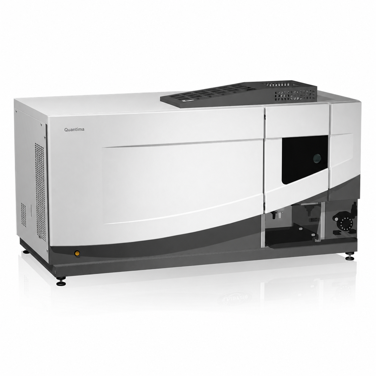
ICP-OES is an instrument used to identify and measure elements in a sample. It uses argon plasma as a high-energy source to excite atoms and ions. These atoms and ions then emit light.
The optical system measures the wavelength and intensity of this light. The instrument then uses this information to calculate the concentration of each element.
One important advantage of ICP-OES is that it can measure many elements from the same sample. It is commonly used in environmental laboratories, metal testing, oil and petrochemical analysis, food testing, and research laboratories.
For more information about the instrument, see ICP-OES for multi-element and metal analysis.
What Is ICP-OES and What Can It Measure?
ICP-OES stands for Inductively Coupled Plasma Optical Emission Spectrometry. It is an elemental analysis technique that measures the light emitted by atoms and ions after they receive energy from plasma.
ICP-OES can measure many metals and other elements, such as Fe, Cu, Zn, Ni, Cr, Pb, Ca, Mg, and P. The elements that can be measured depend on the instrument, sample preparation, and analytical method.
Common samples include water, wastewater, digested sample solutions, lubricating oils, raw materials, and industrial products.
What Do ICP and OES Mean?
ICP is the part of the system that creates argon plasma. The plasma provides energy to the atoms and ions in the sample.
OES is the process of measuring the light emitted from these atoms and ions.
Each element has its own specific wavelengths. The instrument uses the position of the spectral lines to identify the element and uses the signal intensity to calculate its concentration.
You can learn more about optical measurement from What Is a Spectrometer?
Main Parts of an ICP-OES Instrument
ICP-OES analysis depends on several important systems, including the sample introduction system, plasma system, optical system, detector, and software.
Each part can affect the stability and quality of the analytical results.
Sample Introduction System
For liquid samples, the sample introduction system normally includes a pump, nebulizer, and spray chamber.
The nebulizer changes the liquid sample into small droplets called an aerosol. The spray chamber then removes larger droplets and allows suitable small droplets to enter the plasma.
The sample introduction system should match the sample matrix. Samples with high salt levels, high viscosity, or organic solvents may require a different configuration from normal aqueous samples.
The system can also be selected based on the specifications of the ICP-OES instrument.
Torch, Argon Plasma, and RF Generator
The torch is the area where the sample aerosol enters the plasma.
The RF Generator supplies energy to create and maintain stable argon plasma.
Inside the plasma, the sample goes through several processes. The solvent is removed, the sample becomes vapor, atoms are formed, and some atoms and ions are excited to a higher energy level.
These excited atoms and ions later emit light that can be measured.
Optical System and Detector
The light from the plasma contains many spectral lines.
The optical system separates the light by wavelength so that the instrument can measure the correct wavelengths for the target elements.
The detector then converts the light into electrical signals and sends the data to the software.
Optical resolution is important because some spectral lines are very close to each other. More information about this principle can be found in Spectrometer Basics.
How ICP-OES Works from Sample to Final Result
The ICP-OES working principle is a continuous process. It starts when the sample enters the instrument and ends when the software calculates the concentration of each element.
The process can be divided into six main steps.
Step 1: Convert the Liquid Sample into an Aerosol
The liquid sample is pumped into the nebulizer.
The nebulizer uses argon gas to change the liquid into very small droplets called an aerosol.
A stable and consistent aerosol helps keep the amount of sample entering the system steady during analysis.
Step 2: Remove Large Droplets Before the Plasma
The aerosol passes through the spray chamber.
The spray chamber removes large liquid droplets and allows only suitable small droplets to enter the torch.
This process also helps reduce the amount of solvent and sample matrix entering the plasma.
Too much solvent or matrix can affect plasma stability and analytical results.
Step 3: The Sample Changes Inside the Plasma
When the aerosol enters the plasma, the solvent is first removed.
The remaining sample then changes into vapor and forms atoms.
The high energy of the plasma excites some atoms and ions to higher energy levels.
This is an important step before the atoms and ions emit light.
Step 4: Atoms and Ions Emit Element-Specific Light
When excited atoms or ions return to a lower energy level, they release energy as light.
Each element produces a specific set of wavelengths.
This allows the instrument to identify an element from the position of its spectral lines.
This principle is the basis of elemental analysis using Optical Emission Spectrometry.
Step 5: The Optical System Separates the Light and the Detector Measures It
The light from the plasma enters the optical system.
The system separates the light into different wavelengths. The detector then measures the intensity of selected spectral lines for each element.
Selecting the correct analytical wavelength is important because spectral lines from other elements may be close to the target wavelength and may interfere with the result.
Step 6: Software Calculates Concentration from the Calibration Curve
Before measuring an unknown sample, the instrument measures calibration standards with known concentrations.
These standards are used to create a calibration curve.
When the actual sample is measured, the software compares the signal intensity from the sample with the calibration curve.
The software then calculates the concentration of each element in the sample.
Factors That Affect ICP-OES Accuracy
ICP-OES results do not depend only on the performance of the instrument.
Sample preparation, method settings, wavelength selection, and sample matrix can also affect the accuracy and stability of the results.
Sample Preparation and Matrix Effects
The sample must be in a suitable form before it enters the instrument.
Solid samples normally need to be digested or dissolved before analysis.
Samples with high salt content, high viscosity, or organic solvents may require special sample introduction conditions.
Matrix effects can affect aerosol formation, the amount of sample entering the plasma, and the excitation of elements.
For this reason, calibration standards and samples should be prepared under conditions that are suitable for the analytical method.
RF Power, Gas Flow, and Viewing Position
RF Power and gas flow affect the condition and stability of the plasma.
They also affect how much sample reaches the analytical area.
If these settings are not suitable, sensitivity and signal stability may decrease.
The position used to measure the light from the plasma can also affect the signal of each element.
These parameters should therefore be adjusted according to the sample matrix and analytical method instead of using the same settings for every application.
Wavelength Selection and Spectral Interference
One element may have several spectral lines that can be used for analysis.
The analytical wavelength should be selected based on sensitivity, concentration range, and other elements present in the sample.
If another element has a spectral line close to the selected wavelength, spectral interference may occur.
This problem can be reduced by selecting another analytical line, using background correction, or applying another interference correction method supported by the instrument and analytical method.
Standards Related to ICP-OES Analysis
ICP-OES is used with many analytical standards. Some standards describe methods for specific types of samples, while others relate to the instrument or laboratory equipment.
It is important to understand what each standard is designed for.
| Standard | Description |
| ISO 11885:2007 | A method for measuring several elements in water samples using ICP-OES. It is commonly used for water quality analysis. |
| US EPA Method 200.7 | A method for measuring metals and trace elements in water and waste samples using ICP-AES/ICP-OES. |
| ASTM D1976-20 | A method for measuring elements in water using ICP-AES. It can be used with several types of water samples. |
| ASTM D5185-26 | A method for multi-element analysis of lubricating oils, used oils, and base oils using ICP-AES. |
| ASTM D4951-14(2019) | A method for measuring elements in new lubricating oils and lubricant additive packages using ICP-AES. |
| EN 61326-1:2013 | An Electromagnetic Compatibility (EMC) standard for electrical equipment used for measurement, control, and laboratory applications. |